It’s surprising how much of an impact such a small component as a programmable logic controller (PLC) can have on the smooth operation of a hyperscale data center. While people rarely see it, the PLC is responsible for making the system function as one, ultimately getting the critical power to where it needs to be.

In a recent hyperscale project, our Power Management Department worked in conjunction with the client team to fully specify and design the PLC control system that monitors and controls the entire critical power system in the data center facility.
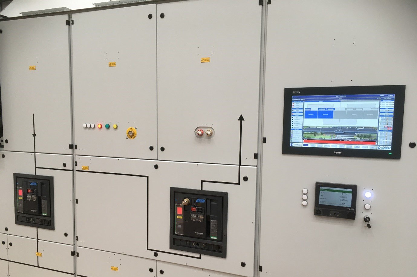
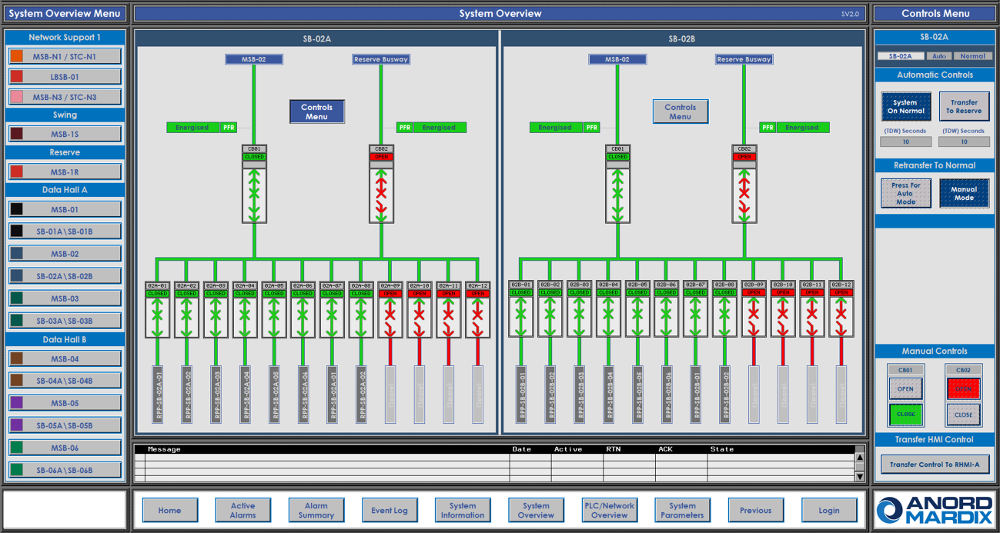
The PLC control system is made up of 20 main switchboards and 24 sub-switchboards. The main switchboards receive the utility power delivered by the on-site substation, this is the site’s default source of power, which is then distributed to the rest of the system. After that, the sub-switchboards distribute the power to the IT systems.
The main switchboards have other power sources available to them, including diesel generator backup. In the event of a main utility feed failing, the system automatically decides where its next source of power should be and reacts accordingly by switching the relevant ACB, MCCB, or starting the backup generators if required.
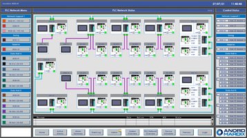
To achieve this control, the PLC system is built up of many different separate parts, all brought together on a redundant fiber-optic network, enabling it to act as one large distributed system. Each PLC takes signals from the monitored pieces of equipment in each switchboard as digital inputs and continually monitors the status; it can issue commands via digital outputs to controlled devices to instruct them when to open and close.
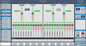
All this information is presented to the data center operators via 21-inch human-machine interfaces (HMI) on each main switchboard so they are fully aware of the state of the system, where the power is derived from, and where it is being delivered to. The HMI also monitors the health of the system: it can warn operators of any abnormal conditions so that quick and decisive action can be taken to correct the problem and prevent any unintentional loss of power.
All this may sound straightforward, but some of the numbers are surprising, especially on a hyperscale project. For instance, the PLC control system on this particular site actively monitors and controls 578 switched devices, which requires a total of 3,584 digital inputs and 1,408 digital outputs to be monitored and controlled.
This, in turn, requires more than 50,000 lines of PLC code and is then presented on 536 pages of bespoke HMI graphics across the entire system. These graphics were developed using a project specific, custom-built symbol library and displays more than 14,000 data points with a total of 8,800 configured alarms and events.
Due to the scale and complexity of the system, the graphical interface was designed with special focus on simplicity for the end user, with smart navigation panes enabling the user to navigate to the desired graphical page within three button presses. It also has pop-up tool tips to help the user during the alarm and fault acknowledgment process, providing access to all project-related technical documentation at the press of a button. These features are just a few examples of how this system supports the user in managing the system as efficiently as possible.
Considering the number of monitored and controlled devices, alarms and events it was imperative these were all 100 percent verified during the strict factory testing process. Custom-built PLC test rigs were used to verify all power failure scenarios to each switchboards, and these rigs simulated the behavior of the remaining switchgear on the system using custom-engineered simulation code. This was then also used during the successful virtual factory acceptance testing phase and provided the client team with the first look at the complete system in action.
The strict testing regime enables the equipment to be delivered to site with full confidence that it is ready for the next phase. This next phase includes networking and connecting the system together with 800 meters of fiber network cabling, 20km of Cat6a network cabling, and 2.8km of control signaling cable ready for further functional testing on site.
Anord Mardix has a long history of providing PLC control systems to data center, critical manufacturing and buildings sectors. We work in conjunction with many suppliers to provide monitoring and control systems that are capable of controlling and monitoring from main utility incomer to final circuit feeding the data hall cabinets.
By integrating cabling and networking equipment within the power pod or power skid, all elements can be fully factory tested. This gives clients the confidence that, once connected to the on-site network, interoperability between modules will be straightforward and the subsequent connection to a head-end system will be much less time-consuming in the commissioning and testing phase than in a conventional build.
In conjunction with our pre-built Power Skid and Power Pod designs, we can provide solutions that include local control and monitoring systems for each pod or elements of site-wide control and monitoring systems. The options are pretty much endless, they can range from all the equipment required to connect to an Anord Mardix or third-party EPMS, to an HMI for each pod that gives visibility of switchgear, UPS, fire alarms and all other systems within the pod.
Find out more about PLCs, Power Skids, Power Pods and more at www.anordmardix.com