
Co-author: Andrew Lozon, senior solutions architect at Ericsson North America
Cloud data center fabrics are made of a network of multi-layer switching equipment. Small fabrics may be deployed as a Layer 2 network infrastructure while larger more scalable fabrics are deployed as a Layer 3 network infrastructure. The Layer 3 fabrics are deployed as a 3-stage or 5-stage Clos architecture.
Automation may be used to configure the fabric expeditiously with consistent and error-free results by handling the complexities of networking configuration and removing that burden from the engineer. The more complex the fabric, the higher the benefit of Fabric Automation (FA).
This article discusses the benefits of FA by examining the complexities of networking configuration.
Future of Data Center Connectivity Supplement
Understanding the data journey
Although there are multiple variations to building a Cloud fabric, a Virtual eXtensible LAN (VXLAN) network with Multiprotocol Border Gateway Protocol (MP-BGP) Ethernet Virtual Private Network (EVPN) control plane will be considered for this evaluation.
Background
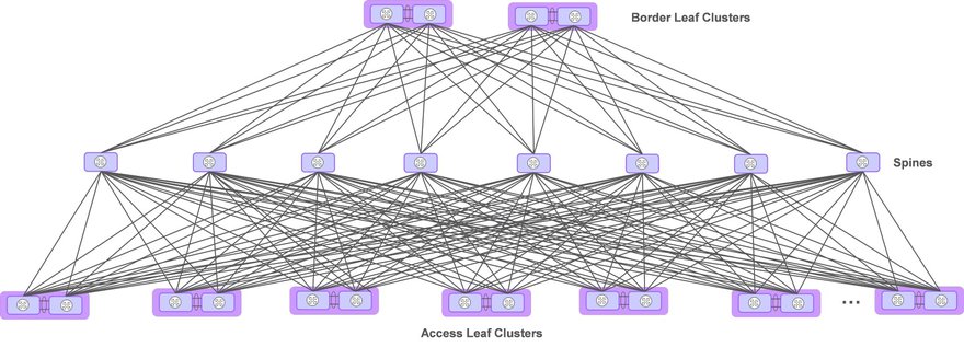
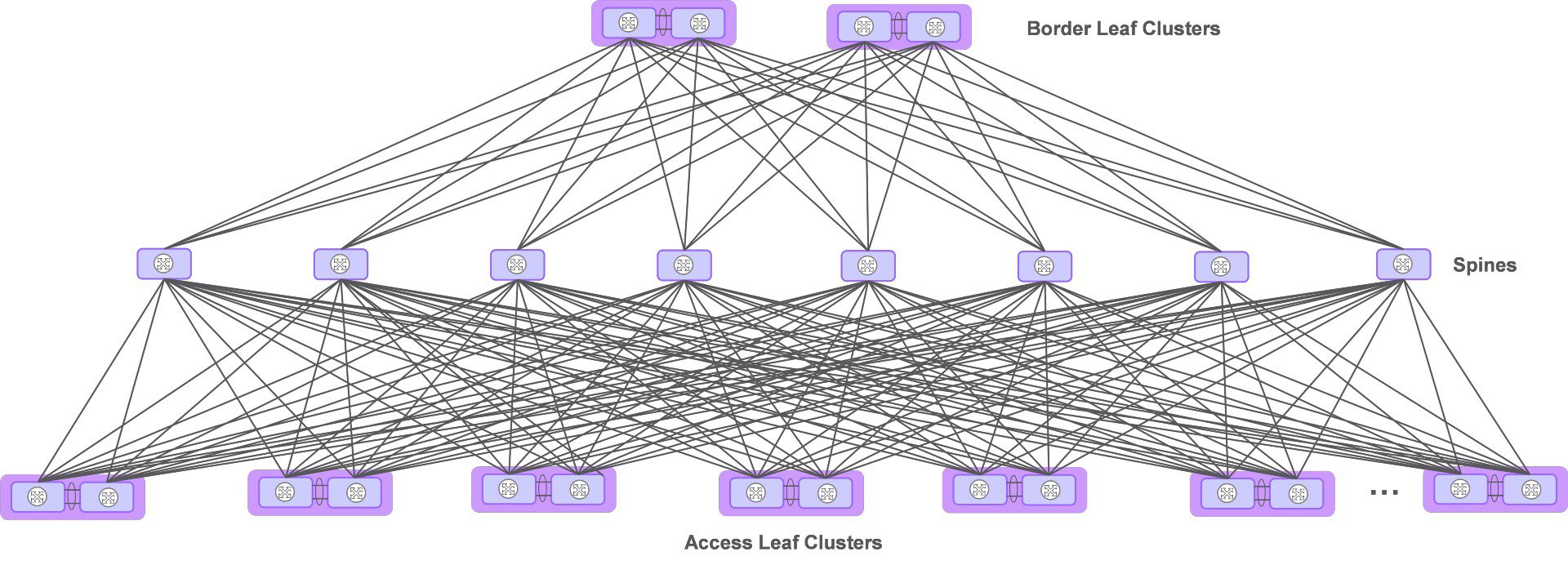
The fabric Clos architecture, derived from Charles Clos’ crossbar switches for telephone call switching, is composed of leaf and spine switches. Leaf switches are subdivided into Access Leaf (AL), or Edge, switches for connecting hosts, or servers, and Border Leaf (BL) switches for providing external access for the fabric. Both physical connectivity and functionality differ between BLs and ALs. The Spine switches are an aggregation layer inter-connecting the BLs and ALs. There may be a single layer of Spine switches as seen in the 3-stage Clos architecture or multiple layers of Spine switches with the addition of a Super-spine layer as seen in the 5-stage Clos architecture. With the 5-stage Clos architecture, Super-spine switches provide full mesh connectivity to the multiple Spine layer switch groups. While the 5-stage Clos architecture reduces the quantity of interfaces, it introduces another layer of networking to the fabric.
AL switches are deployed in pairs in order to provide dual-home redundant connectivity to servers and to Spine switches. The AL switch pair may be inter-connected with 2 or more inter-chassis links (ICL) to create a cluster or may behave as two individual switches. AL switches scale to meet the connectivity requirements of the servers in the data center.
BL switches are deployed in pairs to provide dual-home redundant connectivity to external Provider Edge (PE) routers as well as internal Spine switches. BL switches inter-connect with 2 or more ICLs.
Spine switches inter-connect leaf switches with each leaf switch connecting to each Spine switch. Spine switches do not connect to other Spine switches at the same layer.
Data fabric layers
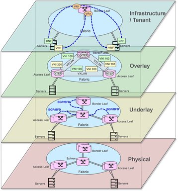
The data fabric is divided into four logical layers comprising physical, underlay, overlay, and infrastructure / tenant. FA is dependent on an established physical layer and creates the underlay network, the overlay network, and the infrastructure / tenant networks.
- Physical
The physical layer includes all the network cabling to inter-connect servers to ALs, ALs to ALs, ALs to spines, spines to BLs, BLs to BLs, and BLs to PEs. This connectivity is a pre-requisite prior to initiation of the FA. Nodes enabled with Link Layer Discovery Protocol (LLDP) within the fabric, transmit information to each of its neighbors which include chassis, port identification, system name and description, and VLAN names. The FA takes advantage of LLDP to create a topology of the fabric network connectivity. From the information gained via LLDP, the multitude of point-to-point (P2P) connections may be automatically configured. VLAN IDs, if used, are selected from a pre-defined pool, and assigned to each interface. P2P IP subnets are created, where each set of IP addresses are allocated from a pre-defined pool.
- Underlay
The fabric underlay establishes the routing and link management infrastructure to ensure reliable and efficient transport of packets across the fabric. Each routing system needs configuration information to ensure proper connectivity with neighbors. Routing parameters include IP addresses, timers, network identifications such as Autonomous System Numbers (ASN). A link management protocol such as Bidirectional Forwarding Detection (BFD) accompanies the routing protocol for fast fault detection with low overhead. Peer IP addresses, transmit and receive timer intervals, multiplier, and options are automatically established.
As can be seen from the figure above, the quantity of interfaces, represented as a line, required to build a Clos fabric architect is significant. Note that each interface represented will consist of one or more physical links as necessary for bandwidth aggregation.
FA takes advantage of the Link Layer Discovery Protocol (LLDP) [IEEE 802.1ab] to automatically map the fabric topology.
Virtual LANs (VLAN) may be used on each physical link to provide logical separation of traffic. FA will assign a VLAN identifier to each link.
Internet Protocol (IP) address assignments are made automatically by FA. Input to FA includes IP address pools of which FA allocates. Pools include nodal loopback addresses, overlay network addresses, e.g., VTEP, inter-chassis links (ICL), multi-chassis trunks (MCT), and other point-to-point interfaces which compose the physical topology.
Link Aggregation Groups (LAG) and its associated Link Aggregation Control Protocol (LACP) are configured on appropriate interfaces which often include Leaf clusters, Leaf and Servers, and may include Leaf and Spines.
The fabric network utilizes a routing protocol, such as Border Gateway Protocol (BGP), to exchange network topology and reachability. Other routing protocols such as Intermediate System to Intermediate System (IS-IS), Open Shortest Path First (OSPF) could be used.
Each switch in the Clos architecture has multiple connections to the adjacent layer. AL switches and BL switches connect to multiple Spine switches and vice versa. Equal Cost Multiple Path (ECMP) algorithms may be incorporated with the routing protocol to provide multiple redundant paths across fabric layers.
To provide fast recovery of failed interfaces, a link integrity protocol such as Bidirectional Forwarding Detection (BFD) is added to assist the routing protocol. This protocol is configured on a per-interface basis and includes timers, timeouts, and other operational provisioning.
Quality of Service (QoS) is established for each fabric port. Each port has physical queues for receiving, buffering, scheduling, and shaping traffic. Each queue is assigned a scheduling algorithm, such as strict priority and weighted fair queuing (WFQ) along with their specific details. A DiffServ Code Point (DSCP) to queue mapping is configured for all ports instructing which queue receives an IP packet based on the IP header’s DSCP value.
Each of the Underlay items above are established repetitively on a per-interface basis thereby making it an excellent candidate for FA.
- Overlay
The Overlay introduces VXLAN tunneling and the associated VXLAN Tunnel End Points (VTEP) to segregate and transport the Cloud infrastructure and Tenant traffic flows. A VTEP is configured at each leaf switch. In the case where a pair of redundant leaf switches are set up as a cluster, the cluster is represented by a single logical VTEP.
VXLAN tunnels are set up between each VTEP which requires communication. This is generally every VTEP to every other VTEP which is a full mesh model. As leaf switches are added, maintaining full mesh connectivity, the quantity of end-to-end tunnels increases as a square function, [V * (V-1)]/2 where V is the number of Leaf Clusters. Each of the Overlay items above are established repetitively on a leaf-pair basis thereby making it an excellent candidate for FA.
- Infrastructure / Tenant
The Cloud infrastructure and Tenant network domains are established by the FA for static environments, Software Defined Networking (SDN), or a combination of the two for more dynamic environments. Both the Cloud Platform infrastructure and Tenants connect to one or more Virtual Private Networks (VPN) outside the Cloud. This manifests in the form of VLANs between the servers hosting the infrastructure and Tenant and the fabric, VLAN to VNI mapping at the fabric edge, Virtual Routers (VR) in the Leaf switches, and corresponding logical interfaces between the BLs and PEs.
As a Cloud infrastructure generally host many Tenants with each Tenant utilizing multiple VPNs, this set up is an excellent candidate for FA.
Life Cycle Management (LCM)
- Audits
FA maintains configuration consistency through audits by comparing the current configuration with its database. Inconsistencies may occur through accidental or intentional alternation of the fabric outside the scope of the FA. If inconsistencies are encountered, then FA corrects the mismatch to align with the intended configuration.
- Hardware management
In the event of hardware replacement, the FA configures the new equipment with the exact information from its database streamlining the replacement process.
Fabric scalability is important as data centers encounter growth. The sequence of adding switches to increase data center capacity follows the same algorithm as adding switches during the initial installation. Therefore, scale-out is a natural capability of the FA. Likewise, a scale-in operation, the removal of switches, or reversal of the scale-out, is also applicable.
- Upgrades
Fabric software upgrades may be an added feature to FA. FA already has a holistic view of the switch components. FA may systematically progress though each switch or groups of switches to upgrade the software version. Traffic is gracefully diverted away from the switch(s) to be upgraded via the use of the routing protocols, taking advantage of features such as Non-Stop Routing (NSR) and Graceful Restart (GR). The new software version is applied to the switch(s). Traffic flow is re-established with the newly upgraded switch(s).
FA maintains the before and after views of the fabric. In the case of an error encountered during software upgrade, FA executes a rollback by replacing the original configuration of each switch.
Conclusion
As Layer 3 Cloud fabrics scale out, the configuration complexity multiplies significantly.
FA allows quicker deployment of data centers to meet the needs of today’s increased commercial pressure.
Once deployed, data centers encounter growth requirements and a constant refresh of technology. FA is well suited to manage scale-out and scale-in operations and is easily adapted to technology changes.
FA provides the following benefits:
- Reduces deployment time and cost
- Reduces human error
- Enhanced Life Cycle Management (LCM) reduces OPEX
FA proves to be both a benefit and necessity in today’s Layer 3 Data Center fabrics.

