Data centers ensure continuous uptime and availability by making sure the power never goes down. But how does a facility maintain the IT load if there is a grid outage or a failure within its power train?
Most data centers worldwide make use of an uninterruptible power supply coupled with a standby diesel generator that kicks in when a grid outage is detected. Let's dive deeper into the uninterruptible power supply technology and how this ensures the availability of the load.
Uninterruptible power supplies (UPSs) sit between the utility grid and the data center and provide power to the facility, either from the grid itself or - in the event of a grid disruption - from a local energy store that can power the facility for a short time.
UPSs are split into two categories - static and rotary - according to their energy source. As the name implies, rotary UPS systems store energy in a rotating flywheel, which acts as a dynamo to deliver power back to the data center when required. Static UPS systems use batteries. We will leave the comparative properties of static and rotary UPS systems to another article.
For now, it's important to understand how manufacturers of UPS systems represent and name their products.
The IEC UPS Standard
The IEC 62040-3: UPS - Method of specifying the performance and test requirements is a standard that ensures vendors use the same naming conventions, helping users choose the best product for their requirements, as well as providing test requirements for performance validation.
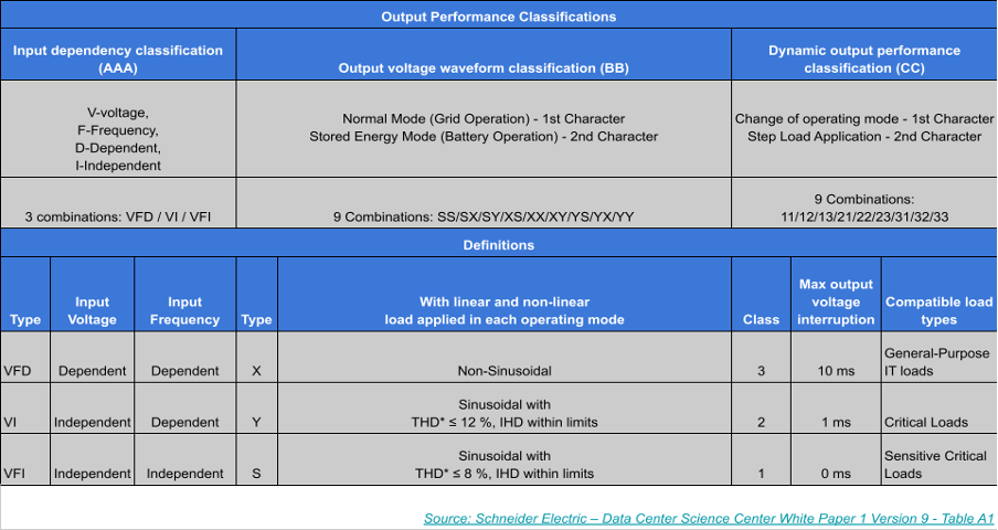
Since UPSs provide power to the facility, their output performance is measured in three ways:
Input Dependency (AAA) - the output voltage is dependent on the quality of the input voltage. There are three classifications in terms of input dependency
Output Voltage Waveform (BB) - given as two characters. The first represents the output voltage waveform when operating in normal mode (using utility power) and the second represents the output voltage waveform when operating in stored energy mode (from the batteries):
- Low total harmonic distortion (THD) sine wave - denoted by S
- Medium total harmonic distortion (THD) sine wave - denoted by X
- Non-sinusoidal wave denoted by Y.
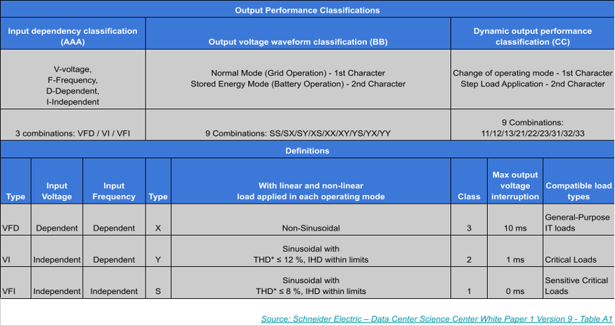
There are 9 possible combinations of output voltage waveforms but the two most common types are sinusoidal (S) and non-sinusoidal (Y). Almost all UPSs rated above 2kVA will be denoted as SS whereas those rated lower than 2kVA will normally be denoted as SY.
Dynamic Output Performance (CC) - the dynamic output performance represents the output voltage variations that happen when the operating mode changes - i.e. switching from the grid to the batteries (first character) and when the load is increased or decreased from the system (second character) These voltage fluctuations fall in three categories:
Modes of Operation
A lot of uninterruptible power supplies can operate in several normal modes that have different output performance characteristics as per the IEC standard.
A double conversion online UPS will have a VFI output performance when operating in normal mode and a VFD output when operating in high-efficiency normal mode. Essentially, a trade-off has been made between the independence of the output and the energy consumption of the UPS.
There are three main modes of operation:
- Normal Mode - The UPS pushes power to the load using the AC input power source (Utility) AND the energy storage device (batteries/flywheels etc) is connected and charging or already fully charged.
- High-Efficiency Normal Mode - The UPS pushes the power directly to the load from the AC input power source with the aim of increased efficiency.
- Stored Energy Mode - The UPS fuels the load with DC current using its energy storage device (battery/ flywheel) because the AC input power source is either experiencing an outage or is outside the allowable voltage or frequency ranges.
The double action of the UPS
The role of the UPS in the facility is not just to keep the IT load up and running in the event of a power outage but to also provide high-quality and clean DC power from its energy storage device. The grid and the utility are subject to multiple power quality issues stemming from the fuel mix, age, and geographical location. The UPS can “clean up” the power source to remove those issues.
The IEEE Standard 1100-2005 standard provides a common nomenclature for the business community and electrical industry when referring to power quality problems and has categorized these into seven categories which are based on the shape of the sine wave:
- Transient
- Interruptions
- Sag / Undervoltage
- Swell / Overvoltage
- Waveform Distortion
- Voltage Fluctuations
- Frequency Variations
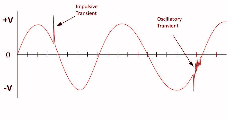
Transients
Transients are the most damaging type of power quality problem and, depending on how they occur, they are split into two categories - Impulsive and Oscillatory.
An impulsive transient is a sudden high peak event that raises the voltage and/or current. Examples of impulsive transients are lightning (and the electromagnetic fields that follow them), ESD (electrostatic discharge) and poor grounding.
An Oscillatory transient is, in simple terms, a transient that causes the power signal to swell up and then shrink down very rapidly. This usually occurs when turning off an inductive or capacitive load - think about a spinning motor that has just been turned off - as the motor’s spin slows down it acts as a generator producing and pushing current through the wider circuit until it reaches a stop.

Interruptions
An interruption is defined as the total loss of the supply voltage or current. Depending on the length of the interruption these can be categorized as instantaneous (0.5 to 30 cycles), momentary (30 cycles to 2 seconds), temporary (2 seconds to 2 minutes), or sustained (bigger than 2 minutes).
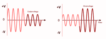
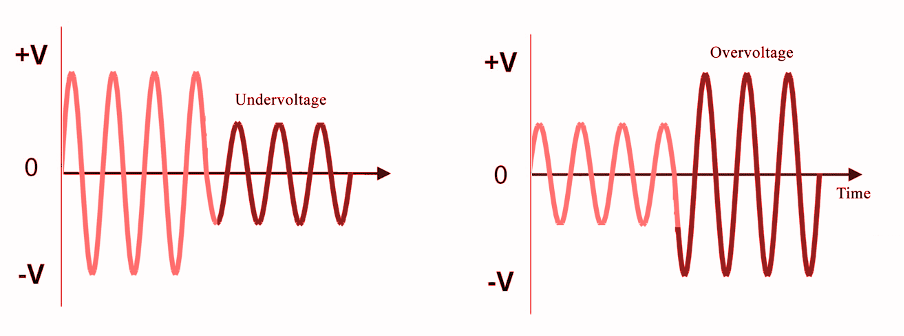
Sag and Undervoltage
A sag is essentially a reduction of the AC voltage at a given frequency for the duration of 0.5 cycles to 1 minute. These are usually caused by system faults or the starting of equipment with heavy startup currents - like a large air conditioning unit.
An undervoltage is the result of longterm problems that create sags. The term brownout is commonly used to describe this and undervoltages will lead to the failure of non-linear loads (like a computer power supply) and can overheat motors.
Swells and Overvoltages
A swell is the opposite of a sag - having an uptick in AC voltage for a duration of 0.5 cycles to 1 minute. Common causes for this are represented by sudden huge load reduction and single-phase faults in a three phase system.
As with undervoltage, an overvoltage is the result of long-term problems that create swells. Continuous overvoltage conditions can increase heat output from devices because of the stress of the additional voltage and thus something highly detrimental to the data center space.
Waveform Distortion
This category includes all distortions present in the sinewave and it’s further categorized as follows:
a. DC Offset - this occurs when DC current is induced into an AC distribution System - most often caused by a faulty rectifier within the current AC to DC conversion systems most data centers will use.
b. Harmonics - this represents the distortion of the fundamental sine wave at frequencies that are multiples of the fundamental one - 120Hz is the 2nd harmonic of a 60Hz fundamental). Effects of this include overheating transformers, tripping of circuit breakers, and loss of synchronization.
Voltage Fluctuations
A voltage fluctuation is essentially a systematic change of the voltage waveform, of small dimensions - around 95 to 105 percent of nominal voltage at a low frequency, usually below 25Hz.
Frequency Variations
This represents the rarest occurrence of power quality problems in stable utility power systems. It does pose a problem for data center sites that have poor power infrastructure and a heavily loaded generator.
That being said, IT equipment is frequency tolerant and not affected by small changes in the frequency of the powertrain that it is connected to. However, frequency variations can cause a motor to spin faster or slower depending on the input power - this will affect its lifespan and performance.
The solution for all the above-detailed problems is represented by the uninterruptible power supply, which takes in AC power from the utility, uses it to charge its energy storage device and then provides a clean sine wave and high-quality power towards the IT hall.
Through a switching mechanism, the UPS maintains the batteries charged and ready to operate even in the event of a prolonged grid outage with no impact to the IT load or the IT equipment.
Redundancy, Criticality, and “N”
We now understand how a facility avoids a utility outage but what if the equipment in the facility itself fails? This is where the redundancy of the UPS system comes into play.
A UPS system that can provide the full load that the IT load needs, and nothing more, is represented as “N,” in which the energy is provided by N subsystems or components.
An “N+1” system has an additional component designed to support a single failure or required maintenance of any other component. 2N represents a fully redundant mirrored system with two complete, independent distribution systems.
These are fully separated and not dependent on each other and this translates to the fact that even if one whole system fails, the other one can safely handle the load. The UPS represents the first line of defense against outages and downtime. Firstly it regulates, converts and cleans the AC utility current into DC power ready to be served to the IT equipment, and secondly by correcting the swathe of quality problems that plague any electrical grid.
There is no one-size-fits-all UPS design - owners and operators need to carefully consider their requirements by measuring factors such as IT load and environment, business aims, and budgets.

