
Artificial Intelligence (AI) is driving the development of transceivers, for fiber, and includes Base 8 and Base 16 technology. This is evolving very quickly with AI as a particular driver. What that means for data center architectural changes is that we are seeing fiber driven directly to the server, due to the increasing need for 50G and above. A common AI use case here is dual 400G transceivers (800G 2XSR4) at the server connected to a single 16-fiber 800G transceiver at the leaf switch (800G VR8).

Interconnect and the value proposition of breakouts for enterprise applications are not often discussed. Customers’ thoughts are more, how do I break down a parallel optic transceiver into usable multiple lanes? However, both are key to the uptake of the technology.
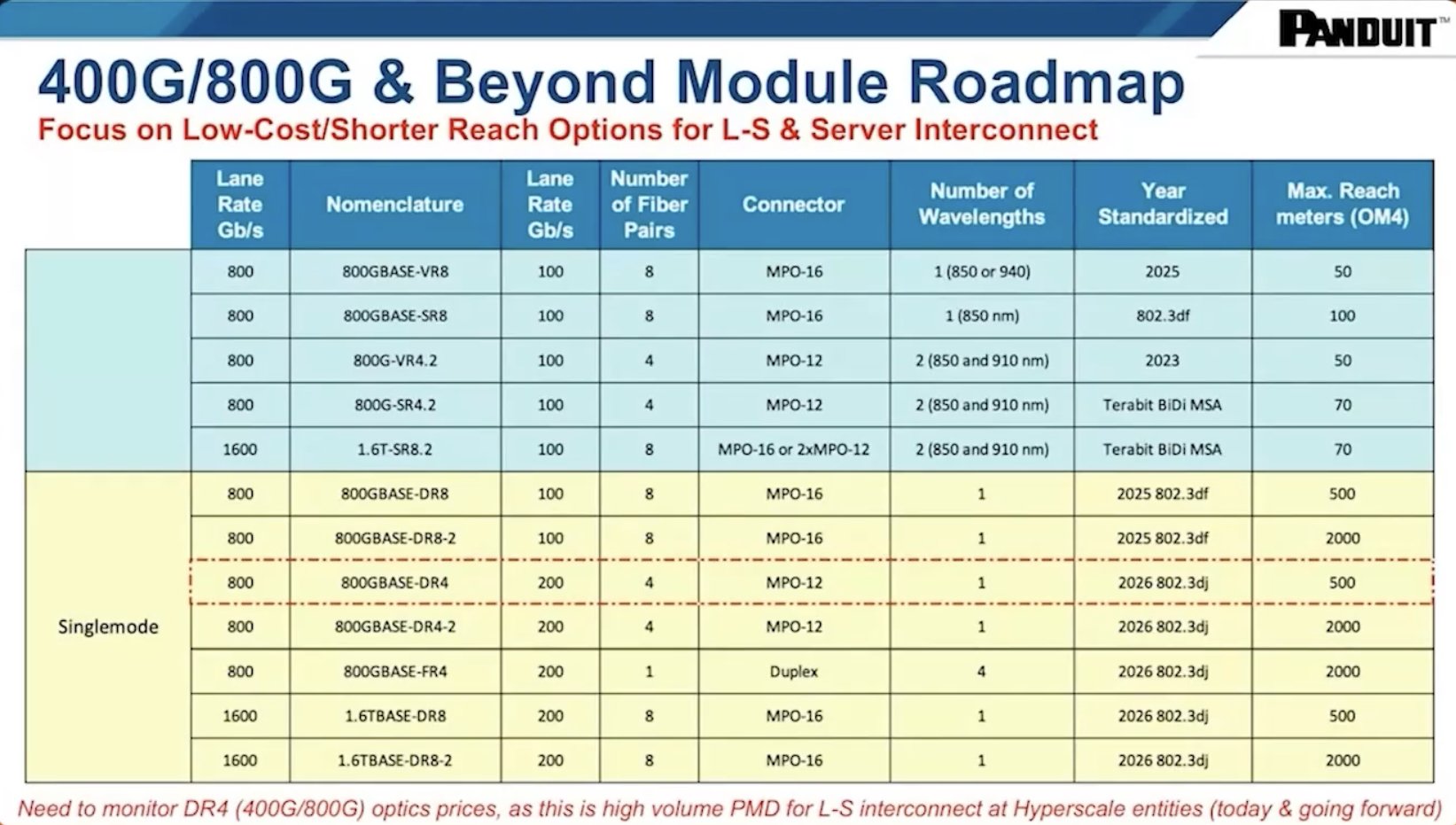
Table 1 illustrates the IEEE roadmap for 400G, 800G up to 1.6T which is central to the discussion around eight-fiber and 16-fiber solutions, as these are the mainstream applications for cloud, enterprise, and AI data centers.
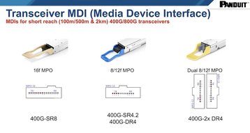
There are three main transceiver types that we see customers using in data centers, the 16f MPO, 8/12f MPO, and dual 8/12f MPO, which provide the breakout capabilities into the lanes for switch to server applications. Firstly, for the 400G SR8, we should note that there are 800G versions out in the market, with a 30m reach, therefore these are not standard reach compliant (the VR8 transceiver is specified by the IEEE standard as 50m). The 400G SR8 is targeted at switch-to-server applications, usually where a chassis-based 400G switch needs to be broken down into 50G lanes, which directly plug into server network interface cards. Here, the full reach of standards-based solutions like VR8 (50m) and SR8 (100m) are not required as a typical switch to server application only requires 15-30m.
We are now moving away from copper beyond 50G, and for 100G or 800G SR8, there is the 8/12f 400G SR4.2 transceiver, which is based on an eight fiber MPO, four lanes of 50G transmit (Tx) and four lanes of 50G receive (Rx) and is the BiDi solution.
The DR4 solution is mainly for hyperscale using leaf/spine interconnect and switch-to-switch solutions. Many Hyperscalers are deploying 800G DR4, however, today some are selecting DR8 solutions for their ability to break out to support two 400G DR4 transceivers.
Transponder manufacturers have also responded to data center requirements using available technology and have developed the dual eight-fiber MPO (2XDR4).
This is basically, two DR4 transceivers turned 90 degrees and enclosed in a single transceiver format (typically OSFP). This is obviously a lower-risk product, as it doubles lane capacity on a recognized format (lower lane rate) and similar connector footprint. It also offers lower power consumption for the same number of lanes and conserves rack space.
Switch-to-switch and switch-to-server configurations
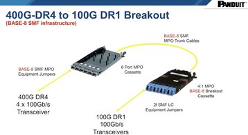
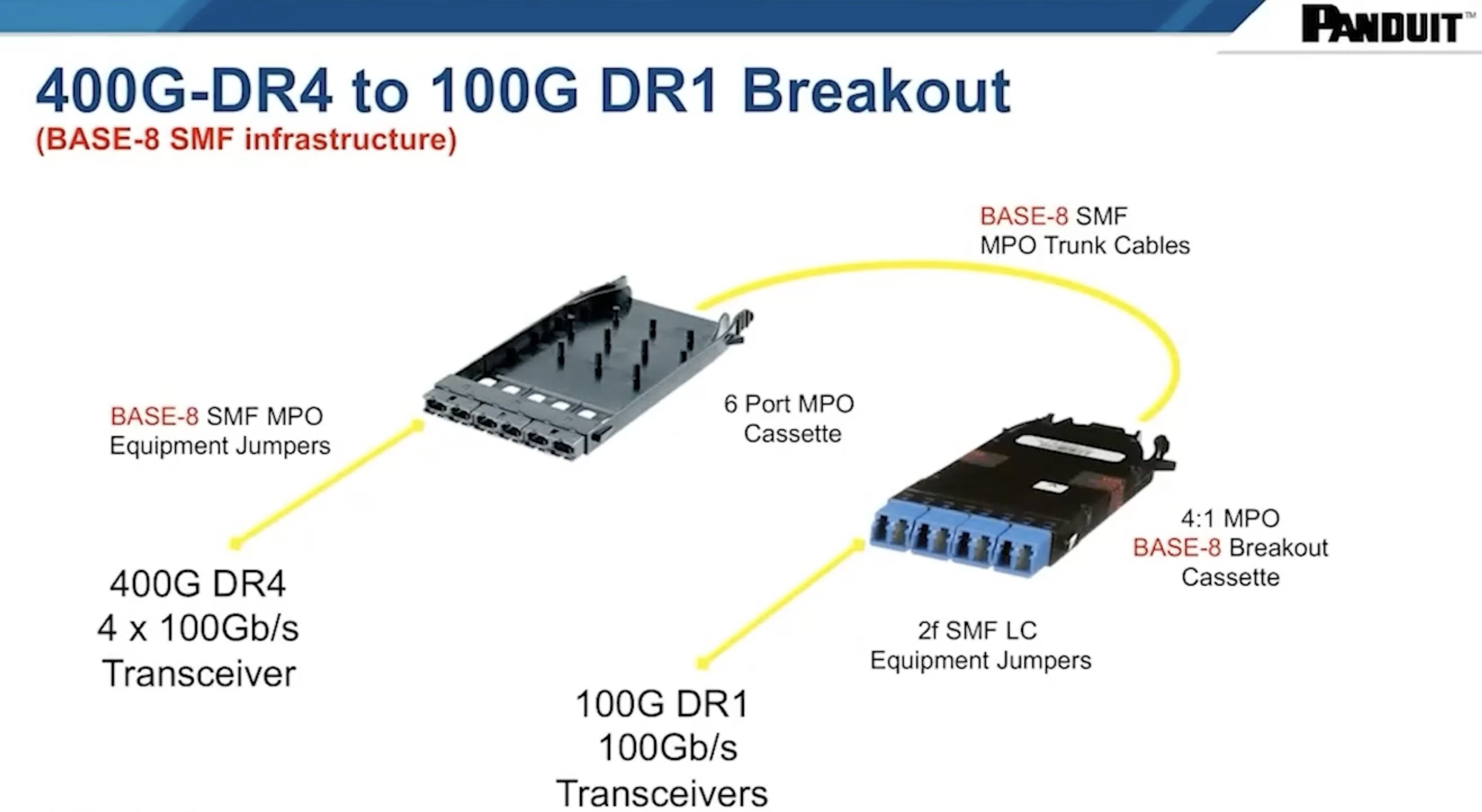
Diagram 1 illustrates the simplicity of the structured fiber cabling for switch-to-switch applications. Customers can use DR4 structured cabling and trunk DR4, eight-fibers into the left-hand panel and into the six-port or eight-port MPO cassette, which is then combined onto one SMF MPO trunk cable to a remote four-to-one (4:1) MPO breakout cassette.
At that point, the solution breaks down into four DR1 lanes for 100G switch equipment distribution. This allows the customer to minimize the footprint of at least one side of the solution and go point-to-point with 100G transceivers.
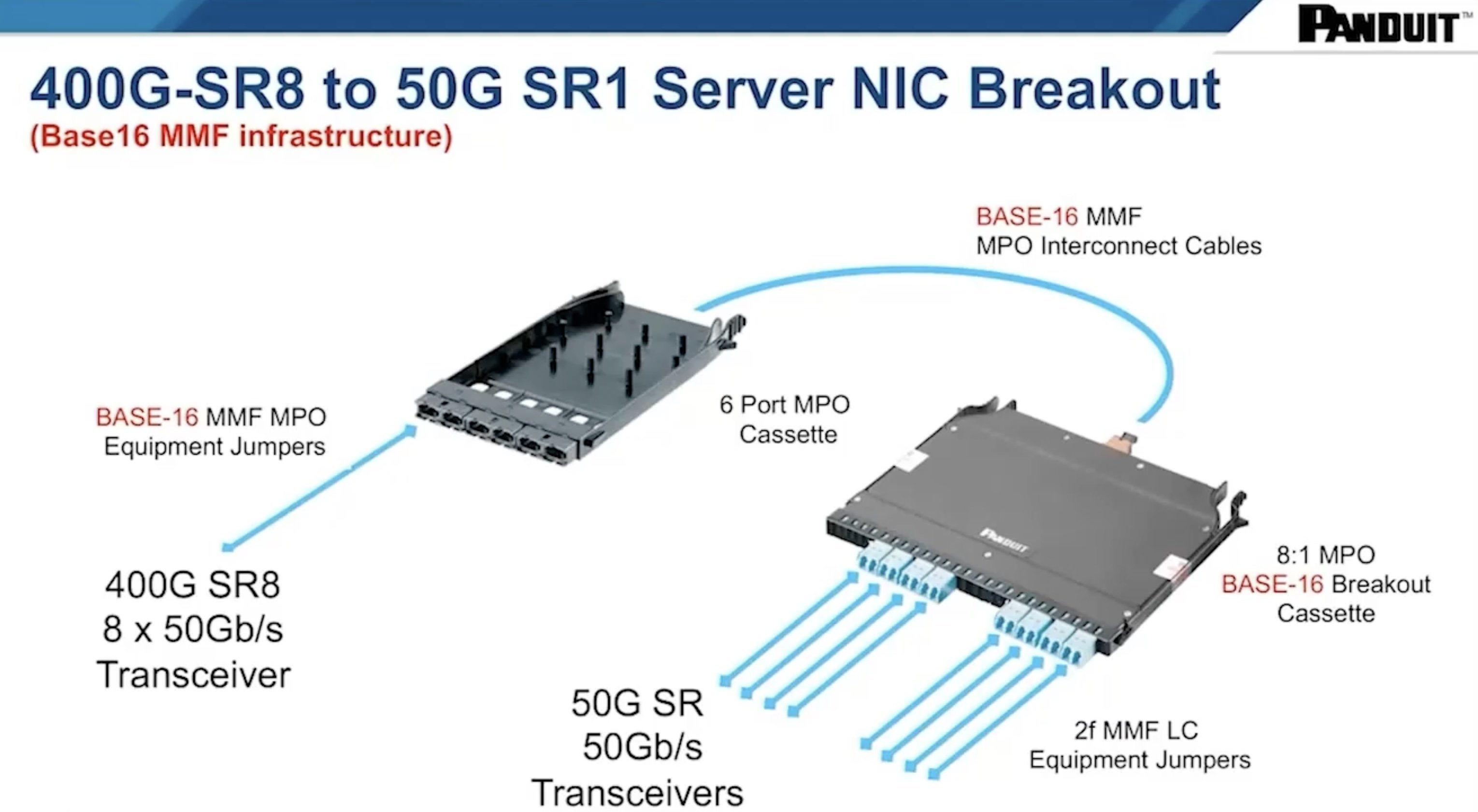
Diagram 2 illustrates a switch to a server application using 400G SR8 transceivers over multimode fiber and supporting 50G SR1 at the servers.

Today this cable plan will support 50G at the server with LC-based NIC cards (and ultimately 100G SR1 & possibly 200G SR1 without cable plant changes).
In this scenario, the customer is supporting eight 50G, or eight 100G Network interface cards (NICs) at the server. This is achieved by either adding a 400 gig SR8 transceiver or 800G SR8 transceiver, the short-reach version plugs into the six or eight-port MPO cassette and the trunk Base 16 fiber trunking assembly connects to the back of the module. This solution offers increased versatility as it can be located on top of server cabinets and distributes LC jumpers directly to the network card in the target servers.
Two market shifts that change the game
A key driver in fiber uptake is the comparative price metric reduction for single-mode fiber transceivers against, what was at times, a 3x cost over interchangeable multimode transceiver solutions. Therefore, scaling solutions using single-mode fiber is not the financially restrictive cost it was, especially where the need for faster and increased amounts of data is essential, as with AI applications and cloud switch-to-switch connections. Many customers today are attracted to the features single mode provides (longer reach and higher lane rate), and for increasing numbers, 400G multimode longer reach solutions are losing out to single mode alternatives, typically for leaf-to-spine fiber interconnect.
An architectural shift from copper to fiber when switching to server interconnect is also taking place. This is partly due to the lower capability (shorter reach) and flexibility of copper (much larger cable diameter), together with the move to higher speed – 50G plus – which has driven fiber to the server NIC.
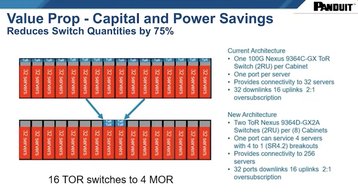
Furthermore, a leap in switch technology offers the capability to massively reduce the number of switches required in a cabinet run. Diagram 3 illustrates sixteen cabinets of 32 servers. The top example ‘current’ shows each cabinet with ToR (top of rack) switching. The second example shows four MoR (middle of row) switches, which are supported by a separate chassis-based switch, and provide identical oversubscription capabilities to the same 512 servers.
As all the active gear is consolidated into fewer chassis-based switches, which are high density due to the parallel optics transceivers providing breakout capability and passive fiber interconnect down to the server cabinets. This moves the topology away from ToR to MoR with a four (SR4) or eight (SR8) way breakout. This layout also offers the capability for cabinet ‘Rack and Roll’ increasing customer opportunities and flexibility.
Upgraded technology and reduced costs
The enhancements being made in connectivity and interconnect are also driving significant infrastructure cost savings. These examples demonstrate that there are savings in deployment and opportunities to enable Rack and Roll. Energy, a key operational cost, is also reduced by the number of switch ports and the number of switches through lane consolidation into single transceiver optics.
By consolidating lanes within a single transceiver, one parallel optics transceiver for example, an SR4 consumes significantly less power than four SR1 transceivers. Also, a native 100G switch, versus a 400G switch, would use significantly less power if it's SR4, and proportionally even less if it's SR8. If this approach is scaled across the 16 cabinet scenarios shown in Diagram 3, it will offer a 60 percent power saving in the switching, providing real value in OpEx and in CapEx, therefore fewer physical switches.
More from Panduit
-
Sponsored Exploring Base-16 technology in the data center
What are the benefits of Base-16 cabling in the data center?
-

-
Sponsored Why Base 16 fiber optic cabling is the future of network infrastructure
Boosted 400G deployment, reduced infrastructure costs, and improved sustainability tracking make Base 16 fiber optics an attractive option