
In this paper, we will discuss some AI cluster back-end network fabric alternatives and show some sample real-world designs. Our aim is not to advocate for a particular selection, but rather to highlight some tradeoffs such that the reader is comfortable with the items worth considering when designing these types of fabrics. In the sample cluster drawing above, the middle rack represents this place in a typical unit of scale (called the scale unit, or SU). These are scaled out to increase cluster size.
Considerations for the networking component in an AI training cluster
To understand the AI back-end cluster traffic needs, we will first very briefly overview the general process that training these large models follows. The general process follows a distribution of a subset of large language models (LLMs) and data to be trained onto a cluster of systems. This process of parallelization involves mechanisms to parse the dataset, the Tensor or n-dimensional array of parameters) to be calculated, establish a pipeline of calculations, and others.
Groups of accelerators in a given cluster work together on that subset that a resource manager has assigned to them. One common resource manager used by almost half the world's supercomputers is the Simple Linux Utility for Resource Management (SLURM) that defines this process, along with the locality of resources (i.e. one common method is to assign the accelerator “local rank” on a each host to be only one silicon stage apart – referred to a “rail”) on the cluster to optimize processing and communications to those accelerators in a given parallel processing group within the overall cluster.
These systems will then perform compute-intensive operations of deriving tensors from extremely large sparse matrices based on the model at hand and the data they were given. When each node completes the work, it needs to exchange the information with all other systems who are involved in that parallel work effort (i.e. not all nodes in the cluster – but those working on that subset of the entire job). These flows are very large, and involve relatively few endpoints who are working on that respective parallel computation – and often called “elephant flows”.
Upon node completion, the individual systems wait for all other nodes to receive all system outputs and use collective communications to synchronize and/or perform some function on the data and share information. These nodes then proceed to the next iteration of calculations. This cycle runs iteratively until the job is completed.
Many factors come into play when considering optimizing the overall job completion time (JCT) in AI training. The iterative process of parsing out the data sets, having many parallel systems train on that subset of data, then merging the results between the cluster members and repeating them during the training often involves thousands of systems and many hours/days/weeks of computation. In this paper, we will focus on that portion of the process where the systems must communicate over an interconnected fabric between their peers. Examples of these communications include sharing data sets, iterative results, and overhead synchronization operations, among many others.
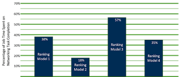
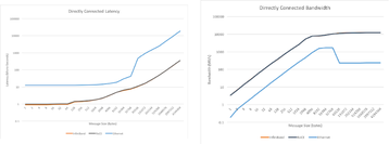
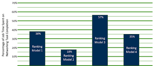
At the 2022 OCP Global Summit, Alexis Bjorlin from Meta shared the information below on the testing performed to quantify the impacts of time spent in these communication mechanisms, as opposed to the core training on the models. Figure 1 shows the results.
While the results show a varying level of impact, the overall conclusion is that the importance of optimizing the system for network I/O can have a meaningful impact on the overall JCT.
Traditional AI backend cluster fabric with InfiniBand
This communication has historically most often utilized an InfiniBand (IB) fabric, which initially was optimal for high-performance compute (HPC) markets, and many of its characteristics complemented the needs within these AI fabrics. Some examples of these optimizations include:
- Remote direct memory access (RDMA)
- Lossless transmission and reception via end-to-end buffer management
- Congestion avoidance
- Fabric-based message aggregation
RDMA
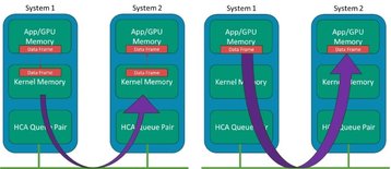
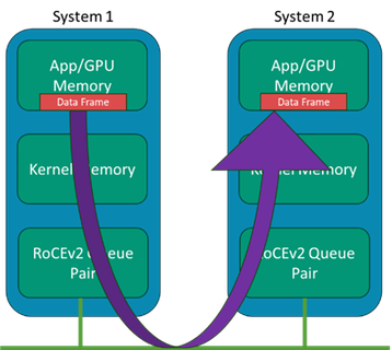
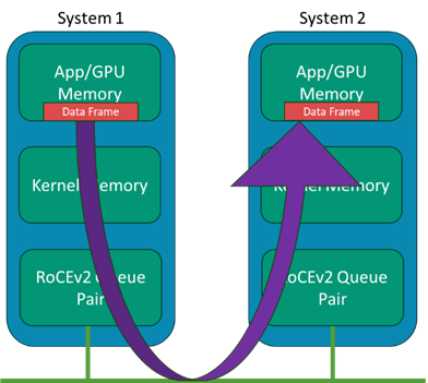
Generally, the RDMA concept has been around in IB for many years, where systems could bypass the kernel data structures and buffers and minimize the intermediate data movement between these layers on a data transmission on the sender side and the reception on the receiver side. Whereas traditional data transmission makes use of the kernel network drivers and stack, which all use the host CPU, the RDMA bypasses those layers and places data directly from the application memory to the wire and likewise from the wire directly to the application memory.
In modern AI systems, the “application” points to the GPU systems' memory space, such that the adapter IO is bypassing kernel memory. In a system with many GPUs but only a few CPUs, we don’t want the CPU copying and processing of frames to become the bottleneck. Figure 2 shows an illustration of the concept with IB host channel adapters (HCA).
Lossless transmission and low latency
Traditional networking of most types involves some assumption of a percentage of the data being lost in transit due to overflowing buffers, packets failing integrity checks due to bit errors, and others.
To help mitigate the risk of buffers overflowing and traffic being lost in the fabric, a credit-based solution is implemented to help back-pressure in the direction of traffic senders such that traffic cannot be forwarded without prior approval. This system ensures a lossless fabric that ensures AI jobs are not stalled due to even a small percentage of traffic loss.
Congestion avoidance
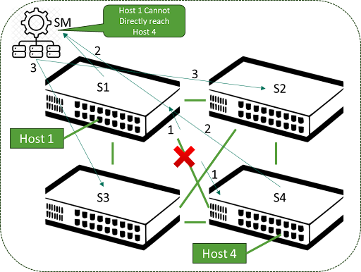
To help traffic transit the fabric and avoid the key hotspots of congestion, the IB switches share information on congestion information along with any link or transceiver outage information to adjust and keep traffic flowing.
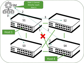
IB architecture mandates an item called a “subnet manager” which has overall responsibility for monitoring the behavior in the fabric via periodic sweeps and messaging between the fabric elements. By itself, there would be a risk of sub-optimal behavior in accounting for link and node outages, but this is handled via adaptive routing, where the forwarding of packets also takes into consideration the queue depth on egress interfaces.
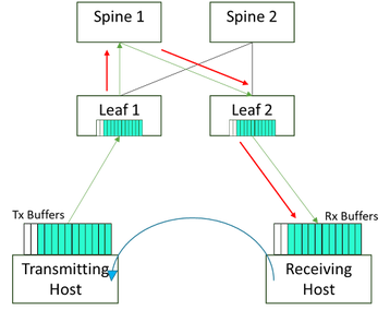
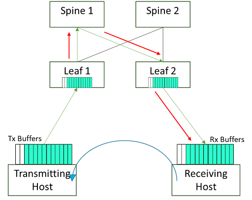
If filling up based on congestion, it will choose another equal-cost multi-path (ECMP) member to send the packets to. This provides a much faster means to re-route traffic around links affected by these events. This is referred to as adaptive routing in an IB fabric but the tradeoff is it does introduce the chance of out-of-order packet arrival – but modern HCA silicon can correct this. Figure 3 shows a simple illustration of this situation where no adaptive routing is present.
Message aggregation
One important area of parallel processing systems is the means to share the outputs of each node within the larger system with its peers. While methods to aggregate these outputs are not new, the extension of these into AI networks is something that came along as these systems grew.
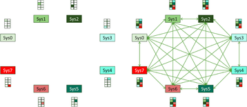
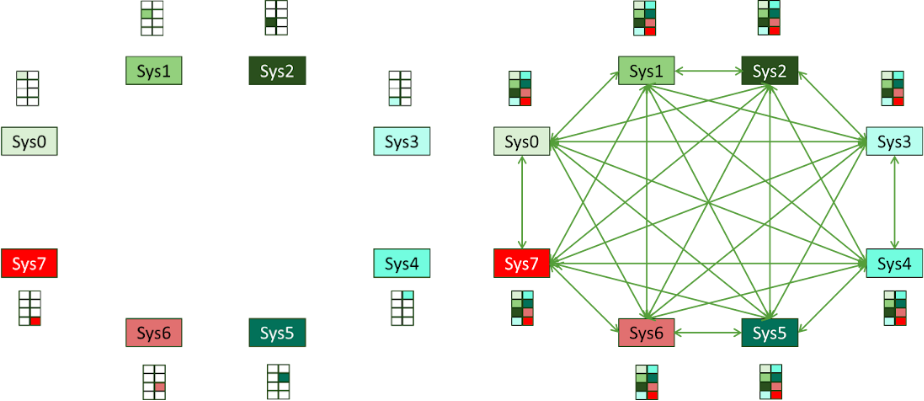
The overall discussion behind methods here is beyond this paper's scope, but we will attempt to summarize the key points based on how this occurs today. To help illustrate the issue, we will use Figure 4.
This leads to many individual nodes communicating on the fabric with many others, and each message has its own connection setup, transfer, and teardown on the hosts and fabric.
The idea of developing a method to simplify this through some intermediate aggregation was added to the IB architecture (although the mechanism does not mandate IB).
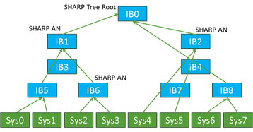
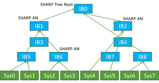
The concept of message aggregation and a more efficient means to minimize the counts of interconnects would be increasingly important as the node count scales into the thousands and tens of thousands of nodes in a cluster. Intermediate nodes performing this message aggregation task, along with the duties of transporting data itself, were conceived and are utilized today.
By employing these techniques of message reduction, the number of messages required between nodes scale is far better than the N*(N-1)/2 of the full mesh.
Mapping these needs into the world of Ethernet back-end cluster networks
Many customers of today's AI solutions continue to deploy with IB as the fabric of choice to realize these benefits. Some customers, however, are evaluating or already using Ethernet fabrics as an alternative to IB for some of the following reasons:
- Ethernet has a very large and open ecosystem
- Wider selection in silicon and open software options
- Industry growth with interconnect speeds and growth trajectory
- Larger scale AI fabrics – even further with routed traffic
- Establishing traffic segmentation to support multi-tenancy needs
- Existing expertise and tooling in deploying, managing, and observing Ethernet
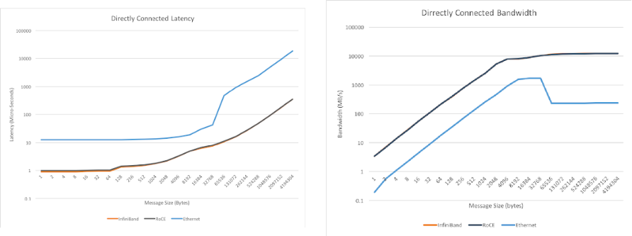
Before we delve into the technical review of how Ethernet technologies are being adapted to meet many of the needs that InfiniBand solves, we will first show a high-level traffic comparison between Ethernet and IB as it exists today from the perspective of I/O performance. On an Ethernet AI Fabric, we have a mix of technologies over and above traditional Ethernet networking to do these traffic performance measurements. Figure 6 shows the results over a variety of message sizes. These tests were done with EDR InfiniBand, and the comparison was 100GE.
There are other studies of varying levels of publication access rules, but the general takeaway was that if we attempt to deploy a general-purpose Ethernet domain the resulting performance would not suffice for the needs of an AI cluster network.
If these infrastructures instead make use of an optimized lossless Ethernet infrastructure, the performance will very closely approximate the performance of InfiniBand from the traffic bandwidth and latency perspectives.
Figure 6 shows that the raw performance from I/O is consistent between these technologies. To get the full picture in a practical AI networking scenario, however, we also need to account for the various optimizations present in the IB world, which would not show on a raw performance graph. A list of these technologies includes:
- Direct GPU to GPU communications
- Raw speed & latency
- Lossless behavior & congestion avoidance
- Message aggregation
- Link failure and re-routing
- Path segmentation
- Load balancing
Direct GPU to GPU communications
As discussed earlier in this paper, InfiniBand uses the RDMA to directly map I/O to/from the wire to the memory on the GPU. In the Ethernet domain, this has been adopted by using RDMA but transported over Converged Ethernet – which means this Ethernet is now converging to transport traffic that traditionally has been on its own fabric (i.e., InfiniBand).
RDMA has been enhanced to offer more scale and physical distance by adding a method to route this traffic in version two of the specification. The result is commonly referred to as RoCEv2 and is ubiquitous in the Ethernet domains and on the network interface cards (NICs) in the systems. An illustration is in Figure 7.
Raw speed and latency
Dell’Oro estimates on the Ethernet port market are on the left, and the 800GE ports becoming dominant over 400GE in 2025 shows the rate of current innovation in speed, with high-speed ports being dominant in the DC by 2027.
As we look further at silicon manufacturer roadmaps, we see 1.6T Ethernet ports gaining rapid penetration in 2027. This pace of growth is not showing any meaningful decline as of late 2023.
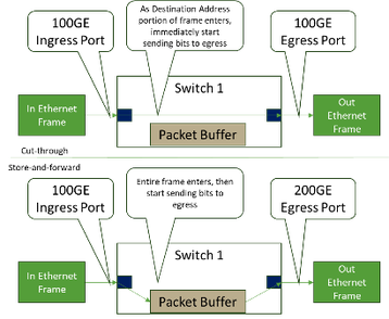
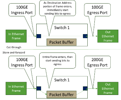
Within Ethernet networks, we define a port-to-port latency for a frame to ingress, be scheduled, and egress a given switching element. In this area, a typical Ethernet element may vary considerably (ranging from ~300ns to ~3000ns) depending on the hardware and what is happening to the frame as it transits the device. On a modern Ethernet switch with equivalent speed ingress to egress ports, cut-through forwarding provides for very low latency, as shown in Figure 8.
IB can be in the range of ~200ns to 300ns for the same hop, meaning this area on fabric IB has an advantage as this transport does not have the same range of application types. Getting the latency as low as possible is desired for many AI networking needs.
There is also an element many use in discussions around “tail latency,” which is the latency of the last message in a chain of messages and is important in AI clusters as all nodes wait for all data to be updated before moving to the following setup.
This may mean nodes are idle while others await the last messages, meaning that is one very important metric over the whole fabric. This level of visibility is more impactful than looking at a switching element latency, and this is where the Ethernet industry is optimizing between the elements themselves and the methods to balance and distribute the traffic at the fabric level. In that realm, the many Ethernet toolsets that exist to optimize these flows bring a latency discussion to a general comparable result between these technologies.
Lossless behavior, congestion avoidance, and path segmentation
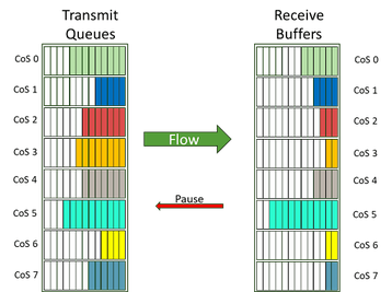
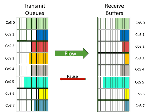
The concepts of enabling lossless behavior and avoiding congestion on Ethernet is a longer discussion and beyond the scope of this document (as is lossless methods in IB). The individual enablers include per-priority flow control (PFC, example in Figure 9) to allow pausing of traffic by class of service.
Another key to managing congestion to allow lossless behavior is shown in Figure 10, where an explicit congestion notification (ECN) is signaled by setting a congestion experienced (CE) value in the DSCP portion of the IP header on these intermediate switches to allow the receiver to inform the sender to slow down so that traffic is not lost.
The mechanisms to monitor, detect, and signal all of this are built into modern switching silicon and are already present in a RoCEv2-aware network fabric. These methods will also monitor congestion on certain links and are used as inputs to other protocols to control traffic on alternative links for effective path segmentation and load balancing (covered below).
Message aggregation: On the fabric versus GPU systems
Today, there is no equivalent function to perform the Message Aggregation function in the Ethernet environment. As an FYI, there is work in the Ultra Ethernet Consortium's In-Network Collectives group to define various sets of functions where these collective operations can be performed. Work on this specification is anticipated for a first release late in 2024.
Intra-DC Border Gateway Protocol (BGP) as a means to approximate IB adaptive routing and Load Balancing on the fabric
Ethernet has used Layer2 mechanisms over its history (Spanning Tree and other more modern methods) to ensure a loop-free path in the fabric for hosts to communicate. When a link or node is lost, the directly connected device will remove entries from MAC tables using the failed pathway.
Traditionally, timers would need to expire for elements in the fabric to look for alternate paths (Static Routing). Alongside the loss of link/device cases, the congestion case was generally not handled until the introduction of PFC, ETS, DCQCN with ECN, WRED, etc., on the Ethernet fabric.
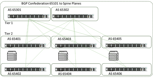
To enhance both the link and node failure recovery, along with effectively adapting for congested links, many end users are now making use of methods like BGP routing within the DC to bring more active adjustments to the fabric in a means somewhat close to what Adaptive Routing on InfiniBand performs depending on if equal-cost or unequal-cost load balancing is utilized.
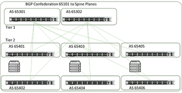
These mechanisms are very effective at tracking and adjusting traffic patterns and re-establishing pathways without human interaction. Figure 11 shows an example of the topology (from a public paper by Facebook).
Summary
Many components of an AI cluster network in this paper discuss the possibility of using Ether InfiniBand or Ethernet in these designs and the tradeoffs.
More from Supermicro
-

Sponsored Fear and Loathing: AI edition
As AI reshapes industries, businesses must weigh risks against the need to innovate and stay competitive by leveraging their data and exploring AI solutions
-
10 best practices for CSP's to scale the data center
Considerations to create a modern data center
-

Sponsored Considerations for AI factories
As AI factories that produce intelligence from existing content, new data centers must consider computing technologies available today and how to remove the heat created by these powerful servers