So far we have explored in detail what the role of the Uninterruptible Power Supply (UPS) is [in Criticality and redundancy in the data center] and we have analyzed the two main types of uninterruptible power supply systems - static and rotary [in Pick your UPS flavor].
It is time to dig deeper into the different types of static UPS systems. Static UPS systems are the most widespread type of UPS and are responsible for keeping the majority of data centers online in the event of a failure from the grid.
As we have learned previously the design of a data center power delivery system is entirely dependent on the continuity requirements of the IT load the data center hosts. As it is usually the case the IT load will require 24/7 availability, the power delivery system will be built to Tier 3 or Tier 4 standards.
Static UPS systems, compared to their rotary counterparts, do not have any moving parts along their power conversion and distribution systems. The most common types of static UPS systems are as follows:
• Standby (or off-line) UPS
• Line Interactive UPS
• Double conversion (or on-line) UPS
We will cover each of these types of static UPS with a description, a topology diagram, their pros and cons as well as the IEC 62040-3 output performance.
The IEC 62040-3: UPS - method of specifying performance and test requirements is an established standard that we have covered previously in issue #50 and further classifies the UPS in three categories - Input dependency (AAA); Output Voltage Waveform (BB); Dynamic Output Performance (CC).

Issue 52 - 3D printing a data center
Plus Red Sea cable attacks, Khazna's CEO, and more
The standby UPS
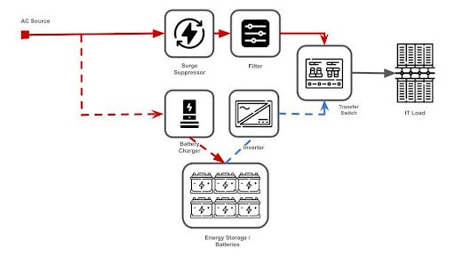
The standby UPS (also called off-line) is commonly used to protect loads such as desktop computers. As shown in the diagram below the transfer switch is set to work on the AC input as the power source (solid line). Should a problem occur with the primary source, the transfer switch changes the power delivery system to switch to the batteries. The name “standby” comes from the fact that the inverter only starts once the primary power path fails - the inverter effectively “stands by” to carry the load.
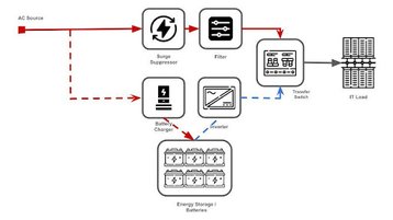
A static UPS is characterized by relatively low cost and a small footprint. It further boasts non-sinusoidal output waveforms and high efficiency. The majority of static UPS systems available on the market also provide surge protection and electrical noise filtering.
The IEC standard classifies the input dependency (AAA) as VFD (Voltage and Frequency Dependent) because the standby UPS lacks circuitry to regulate output voltage or frequency when operating in normal mode.
Further, when it comes to output waveform (BB) the IEC standard classifies this as SY because, in normal mode, it passes the sinusoidal AC input voltage through to the IT load. While in energy mode this type of UPS utilizes a square or step wave inverter (a device that converts DC voltage into AC voltage).
Lastly, the dynamic output performance according to the IEC standard is 33. This is because it typically takes around 10 milliseconds for the system to detect a power failure, move the transfer switch and turn on the inverter. The complete classification for this type of UPS as per IEC 62040-3 is VFD-SY-33.
The line-interactive UPS
Line interactive UPS systems are best suited for protecting IT equipment present in data centers like servers and associated networking equipment like switches and routers.
The block diagram below shows the inner workings of a line interactive UPS and the main differentiation between this and the standby UPS is that the converter (an inverter or a rectifier capable of processing power in both directions) is constantly connected to the output of the UPS. Should the primary source fail, the transfer switch opens and power flows from the batteries to the IT load.
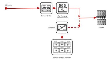
It is important to note that because the converter is constantly connected to the output of the UPS, switching between power sources yields reduced switching transients as well as increased filtering of electrical noise.
The line interactive UPS system design makes use of a tap-changing AVR (automatic voltage regulator) transformer. By adjusting the transformer taps in line with the input voltage the whole system now has voltage regulation. This is of paramount importance within low voltage conditions, otherwise, the UPS would transfer to the battery and in turn shut down the load.
Its small footprint coupled with its high efficiency and high reliability as well as boasting the ability to correct voltage in low or high voltage conditions make this UPS the ideal candidate within the 0.5 to 5kVA power range.
The IEC classification for this type of UPS is VI-SS-31. Because of the AVR transformer regulating input voltage, the standard classifies the input dependency as Voltage Independent (VI).
Output waveforms are classified as SS because it passes the sinusoidal AC input voltage through to the load when operating in normal mode and utilizes a sine wave inverter in stored energy mode. Finally, the dynamic output performance is 31 because it usually takes about 10ms to detect a power failure, open the transfer switch and reverse the power flow through the inverter - which handles step loads very well.
The double conversion
UPS Above 10kVA the double conversion UPS dominates the landscape as it is best used to protect large swathes of servers along with networking and storage equipment.
The types of static UPS we have looked at - line interactive and standby - have two modes of operation - normal and energy storage mode. On the contrary, the double conversion UPS will often boast two additional modes of operation - a high-efficiency bypass mode and a high-efficiency PFC (Power Factor Corrected) bypass mode.
Each mode of operation in a double conversion UPS has slightly different power flows, transfer mechanisms, and IEC classifications.
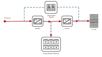
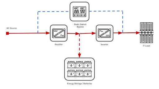
The on-line normal mode double conversion UPS is represented in figure 3. The layout is similar to a standby UPS with the only difference being that the power load is fed through the rectifier (a device that converts AC voltage into DC voltage) and the inverter instead of through a transfer switch fed from the AC source. Essentially the current goes through a double conversion (AC-DC-AC), hence the name.
Should the primary path fail, the rectifier shuts down and the inverter starts drawing power directly from the batteries then feeding the IT load. The primary advantage of this layout is that there is no change in the power path should the primary source fail, no switches open or closed which means the transfer time sits at 0ms. This type of UPS running in on-line normal mode provides almost ideal electrical output performance.
The full IEC standard output performance is classified as VFI-SS-11. This is due to the fact that the on-line double conversion UPS operating in normal mode regulates both output voltage and frequency hence it is a voltage and frequency independent system (VFI). Further, because the sinewave inverter powers the load in every mode of operation the output waveform is classified as SS. Finally, dynamic output performance is 11 because the inverter continuously supplies power to the load without interruption and can also handle step loads very well.
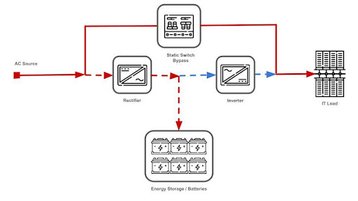
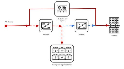
The double conversion on-line UPS operating in bypass normal mode is illustrated in figure 4. The power path through the load happens through the static bypass transfer switch with the rectifier operating in low power mode to keep batteries charged while the inverter is in standby.
Should the primary power source fail, the transfer switch opens, the inverter kicks in and starts supplying the load directly from the batteries.
Operating this type of UPS in bypass normal mode improves the efficiency of the UPS as well as extending its service life since less component stress is being administered along with a reduced heat output. However, operating in bypass mode means that any power quality problems felt in the primary power path will impact the load directly as the inverter is not in operation.
The full IEC standard output performance for this type of UPS in the bypass normal mode is VFD-SS-31.
Because of the use of the transfer switch on the primary power path, it does not regulate voltage or frequency, thus being voltage and frequency dependent (VFD). Furthermore, because both power paths end up supplying an AC sine wave, the waveform output is SS. With the transfer time being around 10ms and the inverter handling step loads well, the dynamic output performance is 31.
The PFC bypass mode differs from the usual bypass mode by keeping the inverter online, providing additional required current to ensure that the load receives only sinusoidal current with a high power factor. This alleviates some of the drawbacks of the previous mode of operation and makes the transfer instantaneous. Because of a 0ms transfer time, the IEC classification for a double conversion PFC bypass mode UPS system is VFD-SS-11.
UPS technology keeps evolving in line with the exponentially increasing demand for clean, uninterrupted, and reliable power delivery across a swathe of industries.
Niched approaches like delta conversion, hybrid conversion or ferro-resonant UPS designs further seek to increase efficiency and cater to all proven use cases.
The systems and technologies outlined have long been at the core of enabling today’s digital society and will continue to play a functional and foundational role in its evolution as the data center landscape keeps responding to the insatiable demand for data.